You may need to adjust the numbers. We can mainly use this module for, more 433mhz RF Transmitter and Receiver module with ArduinoContinue, Hello, welcome back to another interesting tutorial from the SriTu Hobby. The required code for this is given below. Believe it or not this circuit will work with the digital I/O pins of your Arduino or you can use it with the analog pins to detect the amount of water induced contact between the grounded andsensor traces. 5 of them are power straps and the other 5 are sensory straps. The advantages of this photoelectric water, . Remember, pure water is non-conductive, its the minerals that make this work. ENSOR Tutorial| How to use WATER LEVEL SENSOR, How to make a plant watering system with the Nodemcu ESP8266 board and the new Blynk update, Kaiweets Smart Digital Multimeter Unboxing, How to PWM an LED bulb using a Raspberry Pi board, How to blink an LED bulb and how to make an LED chaser using a Raspberry Pi board. We have detected that you are using extensions to block ads. Required fields are marked *. Well use the following Circuit diagram to wire it up. medianet_height = "50";
This sensor module is mainly designed, more Linear hall effect sensor module with Arduino | How it worksContinue, Hello and welcome back. air iot arduino monitoring based project pollution engineersgarage Well do our best to answer your questions. The sensor has ten copper traces, five of which are power traces and five are sense traces. WATER LEVEL SENSOR Tutorial| How to use WATER LEVEL SENSOR, Automatic irrigation and plant watering system using Arduino and soil moisture sensor Hello, welcome back. Water level sensor, LED, LCD 1602 I2C module, Basics Project 008c Water level sensor, LED, LCD 1602 I2C module, Basics: Project 100b How to upload the custom firmware to Ai Thinker A9 GSM GPRS development board, Basics: Project 101a Ai Thinker A9G GPRS GPS development board, Basics: Project 100a Ai Thinker A9 GSM GPRS development board, Raspberry basics: Project 29m Raspberry PI 3 model B board - OpenHAB2 for beginners, Raspberry basics: Project 21b Using Raspberry PI Zero W board with Raspberry PI camera module V2 and, How to post project/information / or comment it, Plug your Adruino Uno board into your PC and select the correct board and com port, Open up serial monitor and set your baud to 9600 baud, Do calibration. labview arduino ultrasonic hc sr04 sensor ni uno distance interface
How can we measure deepest water body levels (like reservoirs, wells etc)? Hence the change in the resistance is inversely proportional to the distance from the top of the sensor to the surface of the water. You can watch it in the video below. Connect the long leg of the LED (the positive leg, called the anode) to the other end of the resistor. The code sketch below is then uploaded to the Arduino and open the serial monitor. Step 2:Program (Please refer to the example code inLEARN -> Get Tutorials on ourwebsite). Connections for Water Level Sensor and Arduino. Finally, if you want to make it more advanced then add an LCD screen to display the output.
water tank arduino level display open electronics project application well height reads projects activated buzzer catatan HELLO ,TIME IS NOT GEETING RIGHT ..WHAT WILL BE THE SOLUTION [] that.
In this tutorial, we will learn how to make a multi-functional robot using the Arduino platform.
They are described below. We hope you found this project useful! In this tutorial, we will learn, how to control a servo motor using a Raspberry Pi board. Hence, it is recommended to calibrate the sensor for the particular type of water that you plan to monitor. The major issue in the code below is setting the threshold values depending on how you did the calibration. In this case we only power the traces when we are taking a reading from the sensor by making the digital pin high. TheArduino IO expansion shieldis the best match for this senor connecting to Arduino. sensor makerlab medianet_crid = "619711275";
Note: As we all know power water is non-conductive. How to make an automatic irrigation and plant watering system using Arduino and soil moisture sensor | Step by step instruction, How to control a servo motor using a Raspberry Pi board, 433mhz RF Transmitter and Receiver module with Arduino, How to make a multi-function Arduino robot, Linear hall effect sensor module with Arduino | How it works, What is a Raspberry Pi | Complete tutorial.
Force Sensing Resistor (FSR) with Arduino. How to Use APDS9960 RGB Infrared Gesture Sensor with Arduino. Moreover, I had been contributing to WordPress Biratnagar as an active member since 2018. The IoT Projects is a hub of electronics projects.
You can delay time according to your needs. But, Actually, the minerals and impurity present in the water make it conductive. This will increase the life span of the sensor. The resistance is inversely proportional to the height of the water. The sensor is slowly submerged into a container with water and the various values are observed on the serial monitor.
Actually, you can follow the LCD connecting to Arduino Instructions to make it more advanced. Usually, you need to change the value in the code to get accurate readings. Lesser the sensor immersed in water will result in higher resistance due to poor conductivity. Can you help with that? To get accurate readings out of your water level sensor. The website is built and Run by passionate enthusiasts, hard-working, and highly positive persons. I love coding, editing, writing and rummaging around Internet. attach and cover it with silicon to the back of sensor. Basically, this is a great piece of code that helps you to learn to use a water level sensor with Arduino. Basically, this water level sensor comes with only 3 pins. With my curiosity and fast learning skills, I managed to learn everything on my own. Your email address will not be published. In this project, you needed these parts : 1.Aruduino Uno R3 (you can also use the other version of Arduino), 3.Arduino IDE ( you can download it fromhere), Understanding the water level sensor module. The resistance value is inversely proportional to the height at which the sensor is submerged in water. Well, now we will learn how this sensor works with Arduino. I am passionate about IoT Projects, Digital marketing, website designing, and reviewing. Now let us create the required program for this. Using the circuit diagram above, note the outputs from the serial Monitor when the sensor is completely dry -vs- partially submerged in the water -vs- completely submerged. This analog water level sensor board has several copper traces on it. This water level sensor also acts as a variable resistor. While reading the Water level sensor output with an analog input pin on Arduino. Also, this tutorial covers how to measure water levels using a water level sensor and display those values on the LCD Display. of In this tutorial I will show how we can interface this kind of sensor with Arduino.
It then displays on the LCD display and the serial monitor. Basically, the series of parallel conductors seen on the sensor acts as a variable resistor (Similar to the potentiometer). medianet_width = "320";
Then create an object as lcd for that library and give the I2c address and the length and width of the LCD display we are using. Then serial monitor and I2C communication are started in the void setup. In this article, were going to do a water level sensor Arduino tutorial. Acoptex.com
You can follow the calibration method to get perfect data to adjust this code numbers.  We always believe in practicality rather than theoretical knowledge. Current can easily pass when more of the traces are bridged. Well go through the entire process of wiring the sensor, and its working principle. \ COM5. Finally, the value is checked in IF condition and the LCD display is 0 if it is empty, 0-350 is low, 350-510 is medium and 510 is high. You will only be emailed about this product! I am a WordPress enthusiast, a hardworking and highly positive person. So we share various electronics IoT Internet Of Things projects from beginners level to the advanced. Hello guys, welcome back to another tutorial from SriTu Hobby. We can monitor factors such as water levels, leaks, and rainfall through this sensor. When this code is uploaded to the Arduino and the sensor is immersed in water, the LCD will display the water level as either LOW, MEDIUM or FULL depending on the height of the sensor submerged. Just make sure that silicon is dry andbe careful do not use silicon on other side as it will damage the sensor. This sensor actually responds to conductivity of the water where it is immersed. Usually, this sensor provides output voltage according to the resistance, so by measuring it, we can determine the water level. Namely, Ground, +5Volt, and Signal Pin. With an ADC on the SunFounder Uno board dealing with that signal, we can know the water depth changes. Please consider supporting us by disabling your ad blocker, Water Level Sensor (Leak Detection Sensor). Your email address will not be published.
All rights reserved. The resistor will pull the sensor trace value high until a drop of water shorts the sensor trace to the grounded trace. 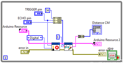 In this tutorial, I will show you how to make automatic, more How to make an automatic irrigation and plant watering system using Arduino and soil moisture sensor | Step by step instructionContinue, Hello and welcome back. Also, when the sensor is submerged in low water, it has a higher resistance due to its weak conductivity. Code for the water level monitoring system using Arduino. [[togetherChouseinfo.price]][[currency]]. Below are the accessories required for this. This is the LCD version of the program code. This is my first article on Raspberry Pi. Finally, we have completed the Water Level Sensor Arduino Tutorial. When the sensor is submerged in more water, it has better conductivity and less resistance. We will meet in the next tutorial. In this sensor, we can see 10 copper straps. Can be used inwater tanksto control water levels. Signal Through this we can get the water level as an analog value. nextion pulse permits graphical Resistor connected for long leg. Save my name, email, and website in this browser for the next time I comment. Water level sensors are used in a number of areas involving monitoring the levels and flow of water like in tanks for irrigation systems, swimming pools and fish ponds. It is recommended to calibrate the sensor for the particular type of water that you plan to monitor.
Take a paper and write down readings of the sensor and the water level in mm or inch (for example, 0mm -0, 5mm - 223, 10mm - 251, 20mm - 294, 30mm - 314, 40mm - 333), Verify and upload the the sketch to your Adruino Uno. Signals and contacts of LCD 1602 I2C module, As you can see on the back of LCD 1602 module there 4 connections: GND (-), VCC (+5V), Serial Data Line (SDA) and Serial Clock Line (SCL), Signals and connections of water level sensor, LED, If you do not have marking on the back of water level sensor module - not a problem. Connect these components using the circuit diagram below. Step 4:Upload the sketch to the SunFounder Uno board. Home RFID Kit V2.0 for Arduino Lesson 15 Water Level Detection. Note: Here you need to add a library. Five of them are power traces and five are sense traces. Also, the backlight of the LCD display is turned on. Sniper Ghost Warrior Intro Upside Down Issue resolved using FFmpeg. The brick is mainly comprised of three parts: An Electronic brick connector, a 1 M resistor, and several lines of bare conducting wires. And use it with the serial console, to get accurate readings out of your water level sensor. This resistance is inversely proportional to the height of the water, that is, the more water the sensor is immersed in, results in better conductivity and will result in a lower resistance and vice versa. First, select the correct board and port and then upload. We will provide you a Program Code examples to get you started with these projects. (adsbygoogle = window.adsbygoogle || []).push({});
. More the sensor immersed in water results in better conductivity and will result in lower resistance. From the schematic above you can observe that the power terminal of the sensor is not connected to the 5V pin of the Arduino as before but rather to a digital pin . in UNO, Project name:Water level sensor, LED, LCD 1602 I2C module. The sensor traces have a weak pull-up resistor of 1 M. As this liquid sensor is able to work at 3.3V which makes it compatible withRaspberry Pi,intel edison, joule and curie. Here are the things to note about this code. In this tutorial, we will learn what is a Raspberry Pi. (Including Digital Clock using OLED Display). Smart Home using DWIN HMI Display & Arduino, AWS IoT Core With ESP8266 & BME280 Sensor, IoT Energy Meter using INA219 Sensor ESP8266 & Blynk, Capacitive Soil Moisture Sensor with ESP8266 & OLED Display, Arduino based Power & Energy Meter using INA219 Sensor, IoT Visitor Counter using ESP32 & Ultrasonic Sensor, IoT Smart RFID Door Lock System Using NodeMCU ESP8266, Interface the Water Level Sensor with Arduino, Arduino water level sensor with LCD Display, Fix MAX30100 Sensor & DIY Pulse Oximeter using Arduino, Multiple LoRa Nodes Communication with Master LoRa Node, LoRa based Two Way Wireless Communication System with Arduino, Arduino based Decibel meter with Sound Sensor, GSM based Fire Alert System Using Arduino and Flame Detector Sensor, Dual Axis Solar Tracker Arduino Project Using LDR & Servo Motors, RFID Based Attendance System Using NodeMCU with PHP Web App, Connect RFID to PHP & MySQL Database with NodeMcu ESP8266, Password Security Lock System Using Arduino & Keypad, IoT Based RFID Attendance System using ESP32, IoT Based Patient Health Monitoring System Using ESP8266/ESP32 Web Server, NodeMCU ESP8266 Monitoring DHT11/DHT22 Temperature and Humidity with Local Web Server, Insert Data into MySQL Database with ESP8266 Development Board, Smart Home using DWIN HMI Display & Arduino | The IOT Projects, Getting started with DWIN HMI Display | The IOT Projects. The sensor produces an output voltage according to the resistance and this voltage is interpreted by a microcontroller to determine the water level. /************************************************. This sensor also works in the same way as the Rain sensor and Soil moisture sensor we have presented in previous articles. This item can easily change the water size to analog signal, and outputanalog value can directly be used in the program function, then to achievethe function of water level alarm.This item have low power consumption, and high sensitivity, which are the biggest characteristics of this module. Code for calibration of the water level sensor with Arduino. How to Install FTDI Drivers for FT232RL FTDI USB to TTL Serial Adapter Module on Windows 10. In this tutorial, we will learn what is the linear magnetic hall sensor and how to connect it to the Arduino. Water level sensor is a module that can sense the depth of water, whose core part is an amplification circuit composed of a transistor and several comb-shape PCB cables. How to control Stepper motor using L298N motor driver and Arduino. It will provide results between 0 and 500 only with the typical water that we get in public places. Please enter your details below and we will send you an email when this item is back in stock. Now upload this code to the Arduino board. It is actually more versatile than you think. Copyright 2022 SriTu Hobby. First, download the I2C library required to control the LCD display and include it into the Arduino IDE. That is, this, more How to make a multi-function Arduino robotContinue, Hello, welcome back. Usually, we can use the water level sensor for many projects. The working principle of the Water Level Sensor is very straightforward. This point is very important to understand because your sensor may be more or less sensitive based on the type of water you have used. In this lesson, we will use a water level sensor to measure the depth of the water and display the result on I2C LCD1602. Also, I will cover a complete description, more What is a Raspberry Pi | Complete tutorialContinue, what if I got this error? This code contains the I2c library first. The resistance varies with the increase or decreases in the water level. To check the data faster than around 100ms you have to turn off the serial output. The numbers I used to work well in my water. I want to add a 5v water pump to this setup that starts when the water level sensor is 50 and stops when the water level is 450. Gravity: Laser PM2.5 Air Quality Sensor For Arduino, Gravity: Analog Turbidity Sensor For Arduino, Gravity: Non-contact Digital Water / Liquid Level Sensor For Arduino, Gravity: Throw-in Type Liquid Level Transmitter, You have choosen:[[togetherChouseinfo.num]], Total amount: VCC This pin should have a potential of 3.3v to 5v. From the values on the serial monitor we can select values to use as our lower and upper thresholds.
Connect the short leg of the LED (the negative leg, called the cathode) to the GND. This item can judge the water level through with a series of exposedparallel wires stitch to measure the water droplet/water size. (Digital Clock example), DS3231 RTC with Arduino. Values should begin from zero when not submerged and then go on increasing as more of the sensor is submerged in the water. For example from the above photo we can use 310 and 510 as our lower and upper thresholds respectively. DIY Lithium-ion 18650 Battery Charger using TP4056 Module. Connecting the water level sensor to Arduino. Water level sensor module is designed for water detection, which can be widely used in sensing the rainfall, water level, even the liquate leakage. You can print this marking. For example, using the same circuit above, and program code below. For me, when the senor is dry (0) and when it is partially merged in the water (~420) and when it is completely merged (~520). The Water Level sensor is super easy to connect because it has only three pinouts. You will see the values like this in the serial monitor.
In this sensor, we can see three main pins. [[currency]][[togetherChouseinfo.price]] Basically, it adds a loop to print to the LCD and move the cursor back on each cycle. The sensor may be more or less sensitive to certain waters. These copper traces are not connected but, they will be bridged by water when submerged in water. The numbers I used to work well in my water.
We can now be able to use the sensor to detect the level of water in a given container for example the set up below shows how the sensor can be connected to an I2C lcd so that we can be able to display the water level on the lcd depending on the thresholds set in the corresponding code. Making a simple water level monitoring system. Leave a comment below if you have any doubts or queries. Ultimately, were just studying the resistance of the impurities in your water. Copyright 2017-2019. When placed in water, the comb-shape cable will change its resistance with the depth of the water and convert the depth signal into an electrical signal. Please disable the Ad Blocker to support creators of content for this site. The following picture shows the needed connections with the Arduino Uno, Watch video here: https://youtu.be/jlb7wUwcA0k. This code is for those who dont have LCD or Dont want to display characters on this project. Now, your LCD screen (or serial console) should be showing the water level. Can be used in factories, commercial complexes, apartments, home. Use a pot of water for that. The conductivity of water depends on the amount of impurities in the water therefore pure water is not conductive. Here the signal pin is an analog output so we will connect it to any analog pin on the Arduino board. I always believes in practicality rather than theoretical knowledge. This sensor works by having a series of exposed traces connected to ground and interlaced between the grounded traces are the sens traces. This tutorial includes how does work the Water level sensor with Arduino. Because, it depends upon the impurities (minerals) present in your water. These traces are not connected but are bridged by water when submerged and act as a variable resistor whose resistance varies according to the water level. So, here is the complete circuit diagram to Interface Arduino Water Level Sensor with an LCD. This code will print the output on the Serial Console. You can study them at the links below. You can review how to use the I2C LCD with Arduino from a previous post using the link below. Actually, This sensor can be used as a water leak detection sensor as well.
Hence it is very easy to interfere with the Arduino board. level arduino water indicator tank This is done to reduce the rate of corrosion of the copper when they are submerged in water and powered for a long time. All rights reserved. Here is a quick list of the components that are required to get started with this Arduino and Water level sensor project: Interfacing the water level sensor is incredibly simple.