Hitachi HD44780 driver compatible LCD screen (162)Bottom View. // Minimum time between send (in milliseconds). Interrupts are enabled for 1 second and then disabled. So the amount of water associated with 1 pulse is equal to 2.22 milli liters. Now we know that 1 pulse represents 2.2 mL. Functional cookies help to perform certain functionalities like sharing the content of the website on social media platforms, collect feedbacks, and other third-party features. An led is also connected to pin # 7 of arduino. The module I bought integrates the TCRT5000 along with an integrated voltage comparator (that I will not use) and a couple of LEDs and resistors. The rising and falling edges of a pulse are vertical. Blow some air through the water flow sensor using your mouth. After activating pull up resistor and declaring pin as input i attached interrupt with it. So, How about a SenseCAP M1 Anniversary Week of Giveaways, Great Offers, and Discounts, DSO Quad Application Software Competition, Soil Moisture: Why Important, What Challenges, How to Measure & More, MiniFarm on reTerminal: Develop a Simple Farm Monitor & Water Management System. This will continue for 1000 milliseconds, and then the noInterrupts() function is called to stop the operation of count_pulse() function. Using a Hitachi HD44780 driver compatible LCD screen and Arduino Liquid Crystal library, you can easily integrate it with your water meter. In this article by Pradeeka Seneviratne author of the book,Internet of Things with Arduino Blueprints, explains that for many years and even now, water meter readings have been collected manually. Change the following pin number assignment if you have attached your water flow sensor to a different Arduino pin: Verify and upload the sketch on the Arduino board: Open the Arduino Serial Monitor and blow air through the water flow sensor using your mouth. written by Bharvi Dixit. I calculated the flow rate in milli liters per minute. Use the 10k potentiometer to control the contrast of the LCD screen. In this article, you will learn how to make a smart water meter with an LCD screen that has the ability to connect to the internet and serve meter readings to the consumer through the Internet. Though i commented all of the code and every statement clearly reflects its meaning but i found out that some of you still need more explanations. 450 pulse for 1 liter, so each pulse means 1/450 liter water flowing through. This website uses cookies to improve your experience while you navigate through the website. This read more, [box type="note" align="" class="" width=""]This post is an excerpt from a book authored by Alberto Paro, titled Elasticsearch 5.x Cookbook. read more, [box type="note" align="" class="" width=""]Our article is a book excerpt from Bayesian Analysis with Python written Osvaldo Martin. You can install your water flow meter to a half-inch pipeline using normal BSP pipe connectors. (OBSOLETE) on older raspbian distributions, Installing python-dev libraries (required for spidev compilation). You can see a pinwheel that is located inside the housing: Pinwheel attached inside the water flow sensor. Arduino + Raspberry is a great little combination, that lends itself quite naturally to the usecase of acquiring raw data from a sensor, transmitting it over a wireless communication link, and finally receiving and processing it as appropriate using a higher level language and enabling further web connectivity. Flow meters works on the principle of hall effect. One can control the valve manually and digitally in order to limit the flow of water through the pipe. Below is a view of the arduino part, integrated inside a small box that is then mounted near the water meter (the USB connector/cable goes to the TCRT5000 module, I just used the 4 available wires in the cable, and happened to have a spare female USB connector lying around. The outer diameter of the connector is 0.78 and the inner thread size is half-inch. In this project, we will use the rising edge. The sensor example sketch counts the pulses from your attached sensor and converts it into liters or gallons per minute and the cummulative water volume. When you use jumper wires with male and female headers, do the following: Water flow sensor connected with Arduino Ethernet Shield using three wires.
Representation of Rising edge and Falling edge in digital signal. Note that the 16-pin header is soldered to the PCB to easily connect it with a breadboard. The water flow volume can be calculated by summing up the product of flow rate and the time interval: The following Arduino sketch will calculate and output the total water volume since the device startup: Pulses per second, water flow rate and in each loop and sum of volume. Then two volatile variables pulsecount and i are used to count pulses and check led status. Its most common/popular one and reviews are 4.5 stared out of 5 for it. Remove all the wires you have connected to your Arduino in the previous sections in this article. Stack the Arduino WiFi shield on the Arduino board using wire wrap headers. I wanted to integrate the ability to display logged data over of specified period of time in my HomeHubTablet display, so I developed an Android graph viewer widget to achieve this. I reused a python library for the RF24 modules from here, I archived it here. // Check that we don't get unreasonable large flow value. To accurately measure water flow rate and volume, the water flow sensor needs to be carefully calibrated. Now on every external high to low transition on pin 3 control will jump to isr CountPulses. Pulses represents a quantity or an amount of water is associated with one pulse or with one rotation of fan. Emerging IoT, AI and Autonomous Applications on the Edge. We can also calculate the liters per second since we have liters per minute. What are discriminative and generative models and when to use which? // Max flow (l/min) value to report. Out of these cookies, the cookies that are categorized as necessary are stored on your browser as they are essential for the working of basic functionalities of the website. Advertisement cookies are used to provide visitors with relevant ads and marketing campaigns. In the code section, we used the following formula, so how did this formula come about? Digital pin 3 of arduino is configured as interrupt pin. To do this, a person has to visit the location where the water meter is installed. The code used for both is almost the same, with only one factor to be modified. When the interrupts() function is called, the count_pulse() function will start to collect the pulses generated by the liquid flow sensor. Use the same pin numbers as used in the previous steps. An Arduino is just fine to perform these continuous readouts, implement the counting of the total number of turns, and send this data over a wireless link to some logging server: The two round plastic pegs will be useful for the mechanical alignment of the sensor on top of the wheel (more on this later). Typically, this type of LCD screen has 16 interface connectors. This great page conveniently provided both an Arduino sketch and a corresponding python script for the raspberry side. Magnet is attached to surface which is movableand hall effect sensor is placed perpendicular to the magnetic fieldof the magnet. LCD +5V pin (pin number 2 from left) to Arduino 5V pin. You can then disconnect your water meter from the computer after uploading the sketch on to your Arduino. Well, in this blog we will tell you basically all the things you need to know about the Water Flow Sensor, which including: We use a water flow sensor to measure the water flow rate. We need only one arduino gpio(general purpose input output) pin to interface flow meter with arduino. The heart of a water flow sensor consists of a Hall effect sensor (https://en.wikipedia.org/wiki/Hall_effect_sensor) that outputs pulses for magnetic field changes. If your water flow sensor requires a supply current of more than 200mA or a supply voltage of more than 5v to function correctly, then use a separate power source with it. Now, reconnect the wires from water flow sensor to the Wi-Fi shield. This mode requires constant power so you will need to connect the sensor to an electrical outlet. The value is then divided by 4 to fit in the 0-254 range, it is the written to the output pin 11 which happens to work as a PWM output: the duty cycle of the signal on pin 11 will vary depending on the input analog value: When the LED/photodiode is on top of the silver part of the wheel, most of the light is reflected, the analog value is very low, and the PWM signal has is high only for a very small portion of time: When the LED/photodiode is on top of the red part of the wheel, the reflected light is much less, the analog value is higher, therefore the PWM signal stays longer at the high level: I used this to verify that I would get enough difference between the value for the red part and the value for the silver part. The water flow meter has threaded ends on both sides. Well hall effect is generation of voltage across a conductor when current is flowing through it and at the same instance it is exposed to a magnetic field. For the final setup, I used a separate 5V power supply. The flow sensor outputs pulses on one rotation. Your email address will not be published. You might be wondering how led checks status? How to use a water flow sensor (Hardware and Code). In some cases, newer water meters are equipped with a pulse output. Set the PULSE_FACTOR to the number of revolutions per cubic-meters (or gallons) of water. Of course, you can usedigitalread()in theLOOPfunction to read the output of the water flow sensor. The number of pulses generated per liter of water flowing through the sensor can be found in the water flow sensors specification sheet. Both the Sketchup model and the exported STL file are available here. The generated pulse can be read by Arduino digital pin 2 and the interrupt 0 is attached to it. This cookie is set by GDPR Cookie Consent plugin. Lets say there are m pulses per liter of water. The result generates an electric pulse that transitions from low voltage to high voltage, or high voltage to low voltage, depending on the attached permanent magnets polarity. Our microcontroller must be working on greater frequency then the flow meters. We calculate the pulses in a specified amount of time.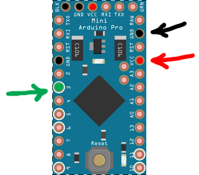 Each This cookie is set by GDPR Cookie Consent plugin. modify /etc/bluetooth/rfcomm.conf to specify MAC address and name the device: and the led on the bluetooth module should not blink anymore. The code becomes: On the (linux) host side, I used a USB bluetooth adapter, connected to the bluetooth module using Ubuntu bluetooth manager and initial pin code 1234. In the above circuit i attached the pulse output pin of flow sensor to arduino digital pin 3. The square and circular sunked surfaces are there to accomodate the bumps present on the sensus 620s front plate, so that the holder can stick perfectly. Again, you can see the soldered 16-pin header. But opting out of some of these cookies may have an effect on your browsing experience. Connect your Arduino to your PC using the USB cable and upload the next sketch. Where 7.5 represents a constant value which is calculated by the manufacture for particular flow sensor 1 represents water in liters and 60 represent seconds or 1 minute. If you aim it at the fastest turning hand on your meter, you can detect pulses or a rate. Firstly i named the pin 3 and 7 of arduino as , Have a technical question about an article or other engineering questions? Syntax is, You can set the starting location to print a text on the LCD screen using following function, syntax is. You can add an LCD screen to your newly built water meter to display readings, rather than displaying them on the Arduino serial monitor. The wiring is extremely simple: connect VCC, GND, and RX and TX (respectively to TX and RX of the Arduino). I bought it in 6 dollars. Flow meter is actually a valve. Securing the connection between the water flow meter and BNC pipe connector using thread seal, Image taken from https://www.flickr.com/photos/ttrimm/7355734996/.
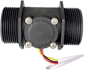


Representation of Rising edge and Falling edge in digital signal. Note that the 16-pin header is soldered to the PCB to easily connect it with a breadboard. The water flow volume can be calculated by summing up the product of flow rate and the time interval: The following Arduino sketch will calculate and output the total water volume since the device startup: Pulses per second, water flow rate and in each loop and sum of volume. Then two volatile variables pulsecount and i are used to count pulses and check led status. Its most common/popular one and reviews are 4.5 stared out of 5 for it. Remove all the wires you have connected to your Arduino in the previous sections in this article. Stack the Arduino WiFi shield on the Arduino board using wire wrap headers. I wanted to integrate the ability to display logged data over of specified period of time in my HomeHubTablet display, so I developed an Android graph viewer widget to achieve this. I reused a python library for the RF24 modules from here, I archived it here. // Check that we don't get unreasonable large flow value. To accurately measure water flow rate and volume, the water flow sensor needs to be carefully calibrated. Now on every external high to low transition on pin 3 control will jump to isr CountPulses. Pulses represents a quantity or an amount of water is associated with one pulse or with one rotation of fan. Emerging IoT, AI and Autonomous Applications on the Edge. We can also calculate the liters per second since we have liters per minute. What are discriminative and generative models and when to use which? // Max flow (l/min) value to report. Out of these cookies, the cookies that are categorized as necessary are stored on your browser as they are essential for the working of basic functionalities of the website. Advertisement cookies are used to provide visitors with relevant ads and marketing campaigns. In the code section, we used the following formula, so how did this formula come about? Digital pin 3 of arduino is configured as interrupt pin. To do this, a person has to visit the location where the water meter is installed. The code used for both is almost the same, with only one factor to be modified. When the interrupts() function is called, the count_pulse() function will start to collect the pulses generated by the liquid flow sensor. Use the same pin numbers as used in the previous steps. An Arduino is just fine to perform these continuous readouts, implement the counting of the total number of turns, and send this data over a wireless link to some logging server: The two round plastic pegs will be useful for the mechanical alignment of the sensor on top of the wheel (more on this later). Typically, this type of LCD screen has 16 interface connectors. This great page conveniently provided both an Arduino sketch and a corresponding python script for the raspberry side. Magnet is attached to surface which is movableand hall effect sensor is placed perpendicular to the magnetic fieldof the magnet. LCD +5V pin (pin number 2 from left) to Arduino 5V pin. You can then disconnect your water meter from the computer after uploading the sketch on to your Arduino. Well, in this blog we will tell you basically all the things you need to know about the Water Flow Sensor, which including: We use a water flow sensor to measure the water flow rate. We need only one arduino gpio(general purpose input output) pin to interface flow meter with arduino. The heart of a water flow sensor consists of a Hall effect sensor (https://en.wikipedia.org/wiki/Hall_effect_sensor) that outputs pulses for magnetic field changes. If your water flow sensor requires a supply current of more than 200mA or a supply voltage of more than 5v to function correctly, then use a separate power source with it. Now, reconnect the wires from water flow sensor to the Wi-Fi shield. This mode requires constant power so you will need to connect the sensor to an electrical outlet. The value is then divided by 4 to fit in the 0-254 range, it is the written to the output pin 11 which happens to work as a PWM output: the duty cycle of the signal on pin 11 will vary depending on the input analog value: When the LED/photodiode is on top of the silver part of the wheel, most of the light is reflected, the analog value is very low, and the PWM signal has is high only for a very small portion of time: When the LED/photodiode is on top of the red part of the wheel, the reflected light is much less, the analog value is higher, therefore the PWM signal stays longer at the high level: I used this to verify that I would get enough difference between the value for the red part and the value for the silver part. The water flow meter has threaded ends on both sides. Well hall effect is generation of voltage across a conductor when current is flowing through it and at the same instance it is exposed to a magnetic field. For the final setup, I used a separate 5V power supply. The flow sensor outputs pulses on one rotation. Your email address will not be published. You might be wondering how led checks status? How to use a water flow sensor (Hardware and Code). In some cases, newer water meters are equipped with a pulse output. Set the PULSE_FACTOR to the number of revolutions per cubic-meters (or gallons) of water. Of course, you can usedigitalread()in theLOOPfunction to read the output of the water flow sensor. The number of pulses generated per liter of water flowing through the sensor can be found in the water flow sensors specification sheet. Both the Sketchup model and the exported STL file are available here. The generated pulse can be read by Arduino digital pin 2 and the interrupt 0 is attached to it. This cookie is set by GDPR Cookie Consent plugin. Lets say there are m pulses per liter of water. The result generates an electric pulse that transitions from low voltage to high voltage, or high voltage to low voltage, depending on the attached permanent magnets polarity. Our microcontroller must be working on greater frequency then the flow meters. We calculate the pulses in a specified amount of time.
Each This cookie is set by GDPR Cookie Consent plugin. modify /etc/bluetooth/rfcomm.conf to specify MAC address and name the device: and the led on the bluetooth module should not blink anymore. The code becomes: On the (linux) host side, I used a USB bluetooth adapter, connected to the bluetooth module using Ubuntu bluetooth manager and initial pin code 1234. In the above circuit i attached the pulse output pin of flow sensor to arduino digital pin 3. The square and circular sunked surfaces are there to accomodate the bumps present on the sensus 620s front plate, so that the holder can stick perfectly. Again, you can see the soldered 16-pin header. But opting out of some of these cookies may have an effect on your browsing experience. Connect your Arduino to your PC using the USB cable and upload the next sketch. Where 7.5 represents a constant value which is calculated by the manufacture for particular flow sensor 1 represents water in liters and 60 represent seconds or 1 minute. If you aim it at the fastest turning hand on your meter, you can detect pulses or a rate. Firstly i named the pin 3 and 7 of arduino as , Have a technical question about an article or other engineering questions? Syntax is, You can set the starting location to print a text on the LCD screen using following function, syntax is. You can add an LCD screen to your newly built water meter to display readings, rather than displaying them on the Arduino serial monitor. The wiring is extremely simple: connect VCC, GND, and RX and TX (respectively to TX and RX of the Arduino). I bought it in 6 dollars. Flow meter is actually a valve. Securing the connection between the water flow meter and BNC pipe connector using thread seal, Image taken from https://www.flickr.com/photos/ttrimm/7355734996/.