Any cookies that may not be particularly necessary for the website to function and is used specifically to collect user personal data via analytics, ads, other embedded contents are termed as non-necessary cookies. Have a technical question about an article or other engineering questions? You also have the option to opt-out of these cookies. As the output goes high, the relay gets energized and the motor starts filling water in the tank. Purpose of this Circuit is to Introduce Transistor as a switch and Water level indication. This category only includes cookies that ensures basic functionalities and security features of the website. Your email address will not be published.
The relay gets de-energized and the motor gets turned OFF. This website uses cookies to improve your experience. This water level indicator project has a very simple circuit consisting of 3 probes which are used for automatic fill and cut of the water supply in tank. Find every electronics circuit diagram here, Categorized Electronic Circuits and Electronic Projects with well explained operation and how to make it procedure and then New Circuits every day, Enjoy and Discover electronics. In order to post comments, please make sure JavaScript and Cookies are enabled, and reload the page. This website uses cookies to improve your experience while you navigate through the website. Data sheet you can get A1015 datasheet here. These cookies do not store any personal information. Your email address will not be published. When you have difficult to know the level of water in the tank you can use this circuit. Save my name, email, and website in this browser for the next time I comment.
Click here for instructions on how to enable JavaScript in your browser. theoryCIRCUIT 2013-2022 | About Us| Disclaimer| Privacy Policy|Contact Us email: info@theorycircuit.com| For Advertisements: ad@theorycircuit.com. 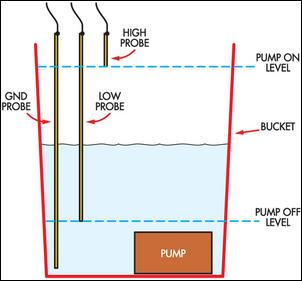
 When the circuit is powered up for the first time the pump should be started automatically if the vessel is empty (or the level is below the required minimum level). But opting out of some of these cookies may affect your browsing experience. It is mandatory to procure user consent prior to running these cookies on your website. If the tank/container is already FULL then nothing should happen. As the HIGH level of the probe is reached, the pump must STOP. The motor remains OFF even though the water level goes below the sensor H. The motor again gets restarted only when the water level fall below sensor L. This cycle repeats every time. Use different height of insulator removed wire as shown in the circuit diagram.
  Simple Single Push Button ON OFF Relay Circuit, Simple Obstacle Identification Sensor Circuit, Simple Audio Amplifier Circuit Using TDA7052, 1 IC LED Flashing Circuit Using 555 Timer. As the water level touches the HIGH level probe, the pump must stop and should not start until the level of water reaches the low level probe. The motor remains ON even though the water level crosses sensor L. As the water in the tank touches the sensor H, the timer IC2 gets retriggered at pin6 through inverters N3 and N4 due to this the output of IC2 goes LOW. We'll assume you're ok with this, but you can opt-out if you wish. These cookies will be stored in your browser only with your consent. Necessary cookies are absolutely essential for the website to function properly. Out of these, the cookies that are categorized as necessary are stored on your browser as they are essential for the working of basic functionalities of the website. The circuit requires working at 12V battery or 230V AC mains using a 12V adaptor. Check out our engineering forums, Getting started with MicroPython on ESP8266, How to use MicroPython with ESP8266 and ESP32 to connect to a WiFi network, Using MicroPython SSD1306 driver to interface an OLED display with ESP8266 & ESP32, How to use ESP8266s sleep modes in MicroPython, MicroPython: Time-related functions, timers & interrupts in ESP8266 and ESP32, MicroPython Reading analog signals in ESP8266 and ESP32, ESP8266/ESP32-based WiFi access point using MicroPython, How to achieve longer MCU battery life with low power sleep mode, Infineons CoolSiC devices support Deltas bi-directional inverter, Qualcomm and Mahindra to provide immersive in-vehicle experiences, Diodes launches high-efficiency synchronous boost converter, Help designing 1.6KW Isolated AC/DC with Constant Current Output, Help with Zero Crossing Detector with the 16F877A code on MPLAB XC8.
The GROUND probe is used for the reference.
Required fields are marked *. (adsbygoogle = window.adsbygoogle || []).push({}); This circuit constructed with transistor A1015, it is a PNP plastic encapsulated transistor. Copyright 2022 WTWH Media LLC. We also use third-party cookies that help us analyze and understand how you use this website. When the water level falls below the level of sensor L, the timer IC2 gets triggered at pin2 through inverters N1 and N2 and the output of IC2 goes HIGH. It will indicate the level of water so you could see the level of water without looking into the tank. Currently you have JavaScript disabled.
All Rights Reserved. theoryCIRCUIT Do It Yourself Electronics Projects. The material on this site may not be reproduced, distributed, transmitted, cached or otherwise used, except with the prior written permission of WTWH Media Privacy Policy | Advertising | About Us. Click here for instructions on how to enable JavaScript in your browser.
This process can also be handled manually by using the switch S1. These are GROUND, HIGH and LOW.