-Since it is needed for calculating the RMS- Then the rest is just a linear transformation to get an output around 220 from the sensor output voltage. Thanks in advance, Hello, yes you can remove that while(true) loop, move the RunningStatistics inputStats; to global declarations, inputStats.setWindowSecs( windowLength ); can be set at setup, you can keep other calculations in the loop please check those articles to find some examples: You can download the ZMPT101B voltage sensor datasheet here. 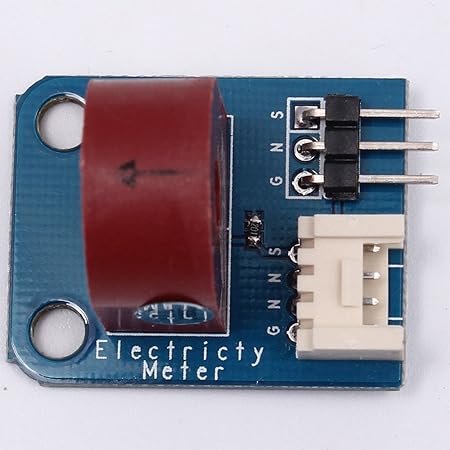 The application is simply to monitor 1-phase 120v or 2-phase 240 volts coming into house. Hello guys , SensorT = analogRead(A2); // read the analog in value: It would be highly appreciate, if you can give me a hand.. I have just replaced the miliseconds check with a delay(1000).
 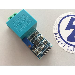 I am not found it, I dont have it that was just a png image. If nothing is connected to the module inputs (module input is 0 volts), your diagram will show a number around 512 (i.e. and can work with 3.3V and you can plug it directly to unsigned long printPeriod = 1000; //Refresh rate i am very grateful if you want to give me your zmpt101b fritzing parts! https://electropeak.com/learn/interfacing-ina219-current-sensor-module-with-arduino/ Find anything that can be improved? First add the intercept until you get current_volts=0 which means: current_Volts = inputStats.sigma() + intercept;, then put the AC voltage on a know value, then set the slope until you get the right value, current_Volts = slope*inputStats.sigma() + intercept;, hello everyone The calibration of the slope and intercept can be pretty tricky, its best to start from the given values then modify them a little bit, otherwise put the AC voltage to 0, remove the slope and intercept completly, current_Volts = intercept + slope * inputStats.sigma(); > current_Volts = inputStats.sigma();. Hi, sorry I didnt tried it with an ESP32, but first the module should be powred by 5v, you should use an external source as the operating voltage of the ESP is around 3.3v I think, use the VCC and GND for power, then for the ESP32 use an Analog input and GND with the Signal and GND from the module, and make sure to use a proper level shifter, I think a voltage divider can do the work. But I want use the arduino project to do the measuring circuit from the electric generator. Hi, * Refer to www.surtrTech.com or SurtrTech YouTube channel for more details const float fFrequency = 50; //Test signal frequency (Hz) I have adjusted the Trim Pot as you suggested ..and the readings look good . but there is always 4095 or 2189 reading even I connect or disconnect cable from module ZMPT101B OR 4 Channel Bi-Directional Logic Level Shifter. Serial.print( current_VoltsS ); //Calculation and Value display is done the rest is if you're using an OLED display, Serial.print( "\tVoltage (T): " ); For the last line to calibrate you can remove it, if you do this. i was stuck in it. (+/-30Amp), ELEGOO Upgraded 37 in 1 Sensor Modules Kit with Tutorial Compatible with Arduino IDE UNO R3 MEGA Nano. boards.
You can directly connect that wire to any of the analog pins of your Arduino board and use the analogRead() function to measure the voltage. you cant use it to measure 2 volts. which can be 2.5, 6 or 11 dB. inputStatsR.setWindowSecs( windowLength ); RunningStatistics inputStatsS; //Easy life lines, actual calculation of the RMS requires a load of coding To use this library, open the Library Manager in Youre seeing this ad based on the products relevance to your search query. It worked, but when i add a delay the measurement become off, do you know why? }, float ReadVoltage(){ Ill just copy it here: This module measures the peak-to-peak voltage. Thats all folks, I hope you like it, be careful and if you have any probel feel free to contact me, dont forget to support the channel by a subscribe. { Hi, For the measures Im using an OLED display, you can checkMy previous tutorial, on how to use it with different examples. RunningStatistics inputStatsR; //Easy life lines, actual calculation of the RMS requires a load of coding Hi, im beginner for high voltage thing, can anyone tell me using this ZMPT101B sensor. or maybe you would recommend some other way to do it instead? ==> if this works you can power the module directly from the ESP32 and use it without a level shifter.
Top subscription boxes right to your door, 1996-2022, Amazon.com, Inc. or its affiliates. lcd.print(volts); When i print directly on serial monitor it give accurate volt but when i am using TM1637 Library and module to print the voltage it give us unstable voltage, i fund the reason is some delay on TM1637 library, Now what can i do for stable value with TM1637 and Filter library for stable value and sigma value, please help, Hi sir, thank you for this wonderful project.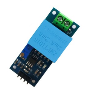 So for (3.3V/Gnd) no AC -> 1.65 its good it means theres the offset and the module is working. I am someone from the old school VB background and am not too familar with the C syntax, also this is very first Arduino project, which I am doing it for my in-house purpose. Need this with ESP8266 12E (NodeMcu)? Hi sir can you help me how can I combine acs712 and zmpt101b in one code with filters library to measuring voltage and current in the same time. Also make sure you connect the output of the sensor to that particular pin. Includes RMS AC Voltage measuring. void setup() { Its actually a formula to calculate the input voltage RMS by using the maximum value of the sensor output voltage. -Since it is needed for calculating the RMS- Then the rest is just a linear transformation to get an output around 220 from the sensor output voltage. Ask me if you need any further information. Apologies for the double post. This is the whole wiring, and as mentionned Im using an 12832 OLED screen you can use it or no, the module is powred by 5v and delivers an analog signal. As we dont have a generator, Im developing a latching relay (Panasonic 50A and 90A relays) system that can wait 30-60 seconds before allowing power into our home. Did you remove that while(true)? * The functions from Filters library permits you to calculate the True RMS of a signal SensorR = analogRead(A0); // read the analog in value: Hi Yassine. Thank you. Do you have any work around for this issue? The module takes the signal we want to measure, here a 220V domestic power, it has around 311V as its peak. because I had the same question toda, and I responded there. AC_Voltage_Measuring:52:3: error: RunningStatistics was not declared in this scope but with esp32 it does not reflect AC values in workable reading. shape signal is second thing, but first there should be change in analog value 1.65v and 3.3v . Library to interact with the ZMPT101B Voltage sensor. Your recently viewed items and featured recommendations, Select the department you want to search in, Gikfun Mini Solder-able Breadboard Gold Plated Finish Proto Board PCB for Arduino Electronic DIY (Pack of 5PCS) GK1009, Gikfun Prototype Shield DIY KIT for Arduino UNO R3 Mega 328P (Pack of 3 Sets) Ek1038x3, Gikfun Prototype PCB Breadboard for Arduino UNO R3 Shield Board (Pack of 5pcs) GK1011. Yes, you actually need to rewrite most of the formulas. #include //Easy library to do the calculations, used for the AC voltage thing, No problem, If you have problem with calibration, you can check my latest tutorial about current sensor ACS712 I use the same method. may i beg your zmpt101b fritzing parts? You just need to use two analog pins to read the output of your modules. Thanks. When BPL switches power back on, many homes get immediately hit with power surges that burn out electrics, fridges, radios, TV, etc. unsigned long previousMillis = 0; void setup() { How do I code for two sensors? Thanks in advanced, The value for out put is sth between 0-5 V. in this situation if I connect the module to 120V and 230V, what we will be the value of output? float slope = 0.0405; // to be adjusted based on calibration testing Filters.h library, as it resets the microcontroller. Hi. Thank you! Now your module is calibrated, the code calibrations will be based on it so try to not change it. The question youre asking is almost the same as an older comment. Our philosophy is simple. Hi.. Can you please explain more about how to derive each value of the equation.. [Veff = (((VeffD 420.76) / -90.24) * -210.2) + 210.2]. I wont to ask you for using zmpt101b for mesuring up to 400v. const int iBluePhaseSensorPin = 2; //Sensor analog input, pin A2 inputStatsS.input(SensorS); // log to Stats function Hello Sir, Would you have any tip to help me? https://electropeak.com/learn/interfacing-zmct103c-5a-ac-current-transformer-module-with-arduino/, Your email address will not be published. volts=analogRead(0)*(5.0/1023.0); Serial.println(volts); How do I use the Sigma function for both? After viewing product detail pages, look here to find an easy way to navigate back to pages you are interested in. Focus on one thing and be the best at it. If I understood you correctly, First I set the Slope=0, put no voltage to the module, and adjust intercept, so the value given in the serial monitor to be 0. I dont have 3 modules to test that for you neither the equipment to get proper 3 phase power from a single phase Well overall its a start because I was stuck on how to drag out that calculation to do side stuff. thank you for your great article. can i use this code with esp32?? inputStats.setWindowSecs( windowLength ); Alfamino Infant Supplement, 14.11 Ounce -- 6 per case. voltage is almost 2.6v to 3.3 v on pin15. In order to calculate the input AC Voltage, you need to find the maximum of the output -Vmax_v- and use the formula given in the second code -step 3 section-. Thanks. In this code, first it finds the maximum measured value (peak voltage) and then converts it to RMS value. There is no significant difference between interfacing one ZMPT101B module and two ZMPT101B modules with Arduino. That is, if nothing is connected to the input and the supply voltage of the module is 5 volts, the output of the module will be 2.5 volts. The problem is that when finished calibrating and supply a different voltage it gives back wrong readings. Thanks. Sir i also want to run other perimeters what can i do inputStatsR.input(SensorR); // log to Stats function Its because reference voltage (Vref) for ADC in ESP32 is 1.1 V. So your 1.65 V translate into 4095, because its out of range. 220 volts). i added a delay(3) inside the loop to simulate other work and got the same problem. I noticed that homes with private generators avoid these surges, as their switching system on generator waits 30-60 seconds after the power comes back on, before switching back over to BPLs grid. You need 2 other variables for all: But you should do it the right way and its very difficult to code, thats why I found a simple library as always to do the work for us . Hello. Test first with only this line Serial.println(analogRead(A0)); add the necessary things like void setup, serial begin., upload the code to the board and open the serial plotter in Arduino IDE, youll see values around 1.65V (2046) maybe.
Learn everything you need to know in this tutorial. You can see that the maximum voltage is somewhere around 600. Hi. i really thanks if you help me out.
Hi, const float fIntercept = -0.04; // to be adjusted based on calibration testing The library Im using is Filters.h, it reduces the amount of work for you, Download here, or from Github. ESP-12 (and ESP8266) has the watchdog(WDT) turned on by default. current_VoltsS = intercept + slope * inputStatsS.sigma(); //Calibartions for offset and amplitude The better way as I said is to use the serial plotter !!! And if possible its better to contact me on facebook page, Can you tell me, from your code , where you got the values below ? // Track time in milliseconds since last reading btw i really need zmpt101b fritzing part for my coursework and i see yours. AC, adafruit, alternatif, Alternative, Arduino, dimmer, easy, Lcd, light, measure, measuring, module, multimeter, OLED, phase, RMS, science, screen, signal, sine, sinewave, single, square, technology, tension, triac, triangular, TRMS, tutorial, voltage, wave, zmpt101b. Hello, Ill try to do in the future but for the moment you can try it yourself: Try making the same thing for both Voltage and Current, use the same method but different variables, and then alternate between them. 3 different currents volts,
Be aware of safety tips when you connect the input voltage (e.g. current_VoltsR = current_VoltsR*(40.3231); //Further calibrations for the amplitude
You can see that the maximum voltage is somewhere around 600. thank you for your conitnous support, I have applied 220v AC , but there is no change in value of Serial.println(analogRead(15)). float current_VoltsR; // Voltage i have used other site code which is same for arduino and ESP32. LiquidCrystal lcd(2, 3, 4, 5, 6, 7); void setup()
I didnt understand your explanation on that in the commwnt section as well. Interfacing DHT11 Temperature/Humidity Sensor with Arduino, Interfacing ACS712 Current Module with Arduino. Mr. Gilmar https://github.com/Abdurraziq/ZMPT101B-arduino This library is compatible with all architectures so you should be able to use it on all the Arduino ==> if this works it means your module is working well, 2) Try this but this time use (3.3V/GND), no AC voltage -> measure -> it should be half 3.3 which is 1.65V. RunningStatistics inputStats; //Easy life lines, actual calculation of the RMS requires a load of coding Hello Surtrtech, Serial.print( B:); I tired to separate them to get be able to do other stuff but I didnt succed for the moment I will try to do it again, because the goal of this tutorial is just measuring. First, the peak value of the sensor output voltage is divided by sqrt(2). #include //Easy library to do the calculations, used for the AC voltage thing
You can see that the maximum voltage is somewhere around 600. I dont know if they are the same because I had it for 2 years. Automation and Electrical Engineer, Electronics amateur trying to share my little projects. https://electropeak.com/learn/interfacing-acs712-current-module-with-arduino/ Because you should remove it if youre using the code in another project. * It permits you to measure any AC voltage up to 250V, BE CAREFUL !!! A non TRMS Multimeter will give you a false reading for a non Sinewave signal too, as you can see the cheap one (blue) compared to our project, its 40V difference which is not good. Hi, i tested it exactly as your code and it works pefectly, but now i want to run it inside a bigger project and i get a lot of noise (same hardware, more complex arduino code). For the intercept and slope, you should modify them depending on your calibration, first dont forget to set the module potentiometer as I showed in the tutorial, just by observing the serial plotter until you get an acceptable shape. You can measure AC voltages up to 250 volts by using this module. Well have L1+N for lights, appliances and small devices, plus L1+L2+N for a cistern pump and A/C compressor. -Since it is needed for calculating the RMS- Then the rest is just a linear transformation to get an output around 220 from the sensor output voltage. The 4096 is the higher value of the Analog to Digital Converter and for it it means 3.3V, make sure its not higher (because it will keep the same value). btw i need zmpt101b fritzing part and i have search but i didnt find the part. inputStatsT.setWindowSecs( windowLength ); while( true ) { is there any change in the code for standard 120v. Hello, Well I tried some few stuffs and I managed to put the calculation part on a separate function that ou can call any time, this will let you do some other side stuffs. Im doing exact the same thing and trying to make ZMPT101B work with ESP32. Am I doing something wrong? How did you calculate the calibration values? float slope = 0.0405; // to be adjusted based on calibration testing
PLease help in it, Hi, I dont know what you mean by perimeters, is it something in the code or materials?? if i cannt so what is the suitble code can i use? lcd.print(Voltimetro); Volts_TRMS = inputStats.sigma()* slope + intercept; I modified the code a little bit because Im about to make a little video concerning the intercept and slope values, now you can for example use this function if modified more to read each sensor separately and store the values on V1, V2 and V3 for example but it should take the sensor input as argument. So. Actually, no, it can only measure AC voltage. After that i supply with known voltage and adjust Slope while I reach the known voltage. All Rights Reserved, Interfacing 3D Printer 20X04 LCD Smart Controller with Arduino, Interfacing DS3231 Real Time Clock RTC Module with Arduino, https://electropeak.com/learn/interfacing-acs712-current-module-with-arduino/, https://electropeak.com/learn/interfacing-ina219-current-sensor-module-with-arduino/, https://electropeak.com/learn/interfacing-zmct103c-5a-ac-current-transformer-module-with-arduino/. But you should know how its done and its easy to find around. */, #include //Easy library to do the calculations, float testFrequency = 50; // test signal frequency (Hz) And we already know that the input voltage RMS is 220V. Just be careful doing a lot of side stuffs can mess with your presicion. https://esphome.io/components/display/ssd1306.html No problem, do you use Serial plotter to see the shape of the signal? In my projetc I will work with Arduino Uno , Display LCD 1206 and sensor ZMPT101B. inputStats.setWindowSecs( windowLength ); but serial monitor help lot to tune ware form but is entirely different in upper corner and it seem to be remain straight , I have try my best to make it pure but upper corners remain same.
Hello Surtrtech, I am having trouble finding a GOOD reliable ZMPT101B module. inputStatsS.setWindowSecs( windowLength ); RunningStatistics inputStatsT; //Easy life lines, actual calculation of the RMS requires a load of coding Hi. inputStats.input(iSensor); //log to Stats function
What I like most is you can send a command back to the Particle board from an app on your phone, web site, etc. please advise what is wrong with this. Hello, Im sorry, Im not familiar with the ESPHome, I think you could use the Adafruit SSD1306 library: and dont forget to declare the pin and its mode. Suggest corrections and new documentation via GitHub. Great video tutorial with written explanation. const float fAmplitudeMultiplier = 40.3231; // some constand required to multiply with voltage, this can be tweeked if required lcd.clear(); The module transformer brings it back to 2.5V peak. Then, you need to derive a formula between that maximum value and the RMS of the input voltage and use it in code 2. 2-Any Suggestions about incorporating the 2 libraries into Home assistant (Adafruit SSD1306 library, Adafruit GFX library)? if you change input voltage, the output voltage will change as well. Also dont forget that the module delivers a sinewave signal not a continuous one, if you just use the serial monitor to see the values it will show strange different values, and it would be difficult to measure them when AC is on. So, I give you the same answer. You can see Pinout of this module in the following image. Another video will be up soon that uses the same method to calculate the alternating current. i suspect is because i do other work in the main arduino loop besides calling this functions.
Arduino IDE and install it from there. Serial.print(fYellowPhaseVoltage);
#include float V=0; unsigned long printPeriod = 1000; // in milliseconds Hello, in the code theres testFrequency = 50 thats for the frequency you can change it to 60, I need to use this on a NodeMCU, but it looks like I have a wrong. Do not use the level shifter, just the module directly with ESP32, POWERED with 3.3V/GND from the ESP and use an analog input. As you can see in the article, this module is designed to measure high voltages up to 250V. Also, remember that ESP32 is a 3.3V microcontroller and 4096 means 3.3V. So the project today is how to measure AC voltage up to 250V, in both 50Hz and 60Hz, using the ZMPT101B, thats the name of the transformer only, but youll find it around with this name or AC voltage sensor. it works Thank you very much. You need to test that yourself. Your email address will not be published. Hello Yassine, Add now an AC voltage and check the shape of the signal, turn the potentiometer unitl you have a shape like I found, you can add a delay after the serial print if you want. 3 of these part: You can do the same process for standard 120V. Serial.println(iPhasePin); what is my next step to calibrating ? RunningStatistics inputStats; Mein was based on an code I made before to measure current so I had to readjust, Hi my problem is that it deos not work ESP32, I am trying to get voltage reading on ESP32. If I get this working, Ill post a .ino file back to you. delay(1000); RunningStatistics inputStats; //Easy life lines, actual calculation of the RMS requires a load of coding unsigned long previousMillis = 0; void setup() { Because I am getting like 440V instead of 220V, thank you. Save my name, email, and website in this browser for the next time I comment. float Volts_TRMS; // estimated actual current in amps The only thing I can mention, is to pay attention to the values, I operate the module with 5V, ESP32 has 3.3V, so try to adapt the values. I cannot adjust the potentiometer, even after 1 hora spinning for both directions. You can see the result in the Serial Monitor. Nevermind, I hit the problem. Serial.println(fBluePhaseVoltage); fVoltage = fIntercept + fSlope * inputStats.sigma(); //Calibartions for offset and amplitude
How did you calculate the calibration values? Can you please explain the linear formula you have given. Connect the module to the Arduino according to the following image. anyone have a library for that module ? inputStatsT.input(SensorT); // log to Stats function, if((unsigned long)(millis() - previousMillis) >= printPeriod) { Hello you can declare other variables, or you can use the same method for both just change the pin, like selecting the sensor A pin or sensor B pin, and it will switch between them. current_VoltsT = intercept + slope * inputStatsT.sigma(); //Calibartions for offset and amplitude
Hello I found this GitHub: Serial.print( current_VoltsR ); //Calculation and Value display is done the rest is if you're using an OLED display, Serial.print( "\tVoltage (S): " ); Thanks for your advice. 11 dB reduces input signal to about 1/3.6, so 3.3/3.6 < 1.1 V and it should show you AC sine on graphs. If the watchdog timer isnt periodically reset then it will automatically reset your ESP8266. When i was trying to remove while it says error while reading First, Thx for this very informative post! I am looking to use ZMPT101B only to monitor if our street power is ON, and therefore do not need to show graphics of sine wave. I have connected ESP32 Pin 2 or Pin 15 with ZMPT101B via shifter. float fRedPhaseVoltage; // stores the voltage in the Red Phase Actually, to measure 2 volts, you dont need to use any module. (check the video or read a code, third code or LCD/OLED code). Any thoughts of how to do this with ZMPT ?
The wave form doesnt change at all. Serial.print( Y:); HiLetgo 37 Sensors Assortment Kit 37 Sensors Kit Sensor Starter Kit for Arduino Raspberry pi Sensor kit 37 in 1 Robot Projects Starter Kits for Arduino Raspberry pi, Variety of Sensors for Your Electronic Projects, All customers get FREE Shipping on orders over $25 shipped by Amazon. Hi. exit status 1 I need to add that when I exceed 15 VAC, I will trigger an output of 5 V on the arduino. Im try to implement 3 phase voltage meter using esp32.. I have used level shifting to protect damages from 5 voltage. If you apply 220V AC to the input, you will see a voltage sinusoidal diagram on the Serial plotter. Can you help me in the project?
Thank you! Hi, current_Volts= current_Volts*(40.3231); if you understand one youll be able to do the others, Thank you Sir,
previousMillis = millis(); // update time every second, current_VoltsR = intercept + slope * inputStatsR.sigma(); //Calibartions for offset and amplitude Hi The 240V is quite important, even though I dont expect a pump to suffer from a power surge, as compared to small electronics, TV, etc. float windowLength = 40.0/fFrequency; // how long to average the signal, for statistics Note: I also got the same values when I tried to separate them like that Im testing on a Particle.io Argon board, as this will send out messages via the Particle.io API, so I can get alerts when power is cut. const int iRedPhaseSensorPin = 0; //Sensor analog input, pin A0 Sensor=2; for 3 inputs. When there is no load on output (nothing is connected to infput), the sensor has an initial voltage (Offset) of VCC/2. Hi. First, please make sure everything is working fine: can we measure 400AC voltage and voltage Frequency ? Since there is while (true) in the code, loop is getting stuck here and current, power, energy etc measurement is not happening. All you need to change is to replace A0 in line 28 and 29 with any of the pins of ESP32. Hello yes you can add the ZMPT101B Right after your main breaker or before the device you want to protect, just dont forget that its max voltage is 250V, and you can use a simple code for examlpe to measure peak to peak, but if your goal is just to know whether theres voltage or not, you can use an optocoupler but always check the Max rating My programming is below , But the Ac Voltage measure is not right. This one might be good for you: This is how its derived: The graph of the sensor output voltage when it has the city electricity as its input is given as the result of the first code.
The application is simply to monitor 1-phase 120v or 2-phase 240 volts coming into house. Hello guys , SensorT = analogRead(A2); // read the analog in value: It would be highly appreciate, if you can give me a hand.. I have just replaced the miliseconds check with a delay(1000). You can directly connect that wire to any of the analog pins of your Arduino board and use the analogRead() function to measure the voltage. you cant use it to measure 2 volts. which can be 2.5, 6 or 11 dB. inputStatsR.setWindowSecs( windowLength ); RunningStatistics inputStatsS; //Easy life lines, actual calculation of the RMS requires a load of coding To use this library, open the Library Manager in Youre seeing this ad based on the products relevance to your search query. It worked, but when i add a delay the measurement become off, do you know why? }, float ReadVoltage(){ Ill just copy it here: This module measures the peak-to-peak voltage. Thats all folks, I hope you like it, be careful and if you have any probel feel free to contact me, dont forget to support the channel by a subscribe. { Hi, For the measures Im using an OLED display, you can checkMy previous tutorial, on how to use it with different examples. RunningStatistics inputStatsR; //Easy life lines, actual calculation of the RMS requires a load of coding Hi, im beginner for high voltage thing, can anyone tell me using this ZMPT101B sensor. or maybe you would recommend some other way to do it instead? ==> if this works you can power the module directly from the ESP32 and use it without a level shifter.
Top subscription boxes right to your door, 1996-2022, Amazon.com, Inc. or its affiliates. lcd.print(volts); When i print directly on serial monitor it give accurate volt but when i am using TM1637 Library and module to print the voltage it give us unstable voltage, i fund the reason is some delay on TM1637 library, Now what can i do for stable value with TM1637 and Filter library for stable value and sigma value, please help, Hi sir, thank you for this wonderful project.
So for (3.3V/Gnd) no AC -> 1.65 its good it means theres the offset and the module is working. I am someone from the old school VB background and am not too familar with the C syntax, also this is very first Arduino project, which I am doing it for my in-house purpose. Need this with ESP8266 12E (NodeMcu)? Hi sir can you help me how can I combine acs712 and zmpt101b in one code with filters library to measuring voltage and current in the same time. Also make sure you connect the output of the sensor to that particular pin. Includes RMS AC Voltage measuring. void setup() { Its actually a formula to calculate the input voltage RMS by using the maximum value of the sensor output voltage. -Since it is needed for calculating the RMS- Then the rest is just a linear transformation to get an output around 220 from the sensor output voltage. Ask me if you need any further information. Apologies for the double post. This is the whole wiring, and as mentionned Im using an 12832 OLED screen you can use it or no, the module is powred by 5v and delivers an analog signal. As we dont have a generator, Im developing a latching relay (Panasonic 50A and 90A relays) system that can wait 30-60 seconds before allowing power into our home. Did you remove that while(true)? * The functions from Filters library permits you to calculate the True RMS of a signal SensorR = analogRead(A0); // read the analog in value: Hi Yassine. Thank you. Do you have any work around for this issue? The module takes the signal we want to measure, here a 220V domestic power, it has around 311V as its peak. because I had the same question toda, and I responded there. AC_Voltage_Measuring:52:3: error: RunningStatistics was not declared in this scope but with esp32 it does not reflect AC values in workable reading. shape signal is second thing, but first there should be change in analog value 1.65v and 3.3v . Library to interact with the ZMPT101B Voltage sensor. Your recently viewed items and featured recommendations, Select the department you want to search in, Gikfun Mini Solder-able Breadboard Gold Plated Finish Proto Board PCB for Arduino Electronic DIY (Pack of 5PCS) GK1009, Gikfun Prototype Shield DIY KIT for Arduino UNO R3 Mega 328P (Pack of 3 Sets) Ek1038x3, Gikfun Prototype PCB Breadboard for Arduino UNO R3 Shield Board (Pack of 5pcs) GK1011. Yes, you actually need to rewrite most of the formulas. #include //Easy library to do the calculations, used for the AC voltage thing, No problem, If you have problem with calibration, you can check my latest tutorial about current sensor ACS712 I use the same method. may i beg your zmpt101b fritzing parts? You just need to use two analog pins to read the output of your modules. Thanks. When BPL switches power back on, many homes get immediately hit with power surges that burn out electrics, fridges, radios, TV, etc. unsigned long previousMillis = 0; void setup() { How do I code for two sensors? Thanks in advanced, The value for out put is sth between 0-5 V. in this situation if I connect the module to 120V and 230V, what we will be the value of output? float slope = 0.0405; // to be adjusted based on calibration testing Filters.h library, as it resets the microcontroller. Hi. Thank you! Now your module is calibrated, the code calibrations will be based on it so try to not change it. The question youre asking is almost the same as an older comment. Our philosophy is simple. Hi.. Can you please explain more about how to derive each value of the equation.. [Veff = (((VeffD 420.76) / -90.24) * -210.2) + 210.2]. I wont to ask you for using zmpt101b for mesuring up to 400v. const int iBluePhaseSensorPin = 2; //Sensor analog input, pin A2 inputStatsS.input(SensorS); // log to Stats function Hello Sir, Would you have any tip to help me? https://electropeak.com/learn/interfacing-zmct103c-5a-ac-current-transformer-module-with-arduino/, Your email address will not be published. volts=analogRead(0)*(5.0/1023.0); Serial.println(volts); How do I use the Sigma function for both? After viewing product detail pages, look here to find an easy way to navigate back to pages you are interested in. Focus on one thing and be the best at it. If I understood you correctly, First I set the Slope=0, put no voltage to the module, and adjust intercept, so the value given in the serial monitor to be 0. I dont have 3 modules to test that for you neither the equipment to get proper 3 phase power from a single phase Well overall its a start because I was stuck on how to drag out that calculation to do side stuff. thank you for your great article. can i use this code with esp32?? inputStats.setWindowSecs( windowLength ); Alfamino Infant Supplement, 14.11 Ounce -- 6 per case. voltage is almost 2.6v to 3.3 v on pin15. In order to calculate the input AC Voltage, you need to find the maximum of the output -Vmax_v- and use the formula given in the second code -step 3 section-. Thanks. In this code, first it finds the maximum measured value (peak voltage) and then converts it to RMS value. There is no significant difference between interfacing one ZMPT101B module and two ZMPT101B modules with Arduino. That is, if nothing is connected to the input and the supply voltage of the module is 5 volts, the output of the module will be 2.5 volts. The problem is that when finished calibrating and supply a different voltage it gives back wrong readings. Thanks. Sir i also want to run other perimeters what can i do inputStatsR.input(SensorR); // log to Stats function Its because reference voltage (Vref) for ADC in ESP32 is 1.1 V. So your 1.65 V translate into 4095, because its out of range. 220 volts). i added a delay(3) inside the loop to simulate other work and got the same problem. I noticed that homes with private generators avoid these surges, as their switching system on generator waits 30-60 seconds after the power comes back on, before switching back over to BPLs grid. You need 2 other variables for all: But you should do it the right way and its very difficult to code, thats why I found a simple library as always to do the work for us . Hello. Test first with only this line Serial.println(analogRead(A0)); add the necessary things like void setup, serial begin., upload the code to the board and open the serial plotter in Arduino IDE, youll see values around 1.65V (2046) maybe. Learn everything you need to know in this tutorial. You can see that the maximum voltage is somewhere around 600. Hi. i really thanks if you help me out.
Hi, const float fIntercept = -0.04; // to be adjusted based on calibration testing The library Im using is Filters.h, it reduces the amount of work for you, Download here, or from Github. ESP-12 (and ESP8266) has the watchdog(WDT) turned on by default. current_VoltsS = intercept + slope * inputStatsS.sigma(); //Calibartions for offset and amplitude The better way as I said is to use the serial plotter !!! And if possible its better to contact me on facebook page, Can you tell me, from your code , where you got the values below ? // Track time in milliseconds since last reading btw i really need zmpt101b fritzing part for my coursework and i see yours. AC, adafruit, alternatif, Alternative, Arduino, dimmer, easy, Lcd, light, measure, measuring, module, multimeter, OLED, phase, RMS, science, screen, signal, sine, sinewave, single, square, technology, tension, triac, triangular, TRMS, tutorial, voltage, wave, zmpt101b. Hello, Ill try to do in the future but for the moment you can try it yourself: Try making the same thing for both Voltage and Current, use the same method but different variables, and then alternate between them. 3 different currents volts,
Be aware of safety tips when you connect the input voltage (e.g. current_VoltsR = current_VoltsR*(40.3231); //Further calibrations for the amplitude
You can see that the maximum voltage is somewhere around 600. thank you for your conitnous support, I have applied 220v AC , but there is no change in value of Serial.println(analogRead(15)). float current_VoltsR; // Voltage i have used other site code which is same for arduino and ESP32. LiquidCrystal lcd(2, 3, 4, 5, 6, 7); void setup()
I didnt understand your explanation on that in the commwnt section as well. Interfacing DHT11 Temperature/Humidity Sensor with Arduino, Interfacing ACS712 Current Module with Arduino. Mr. Gilmar https://github.com/Abdurraziq/ZMPT101B-arduino This library is compatible with all architectures so you should be able to use it on all the Arduino ==> if this works it means your module is working well, 2) Try this but this time use (3.3V/GND), no AC voltage -> measure -> it should be half 3.3 which is 1.65V. RunningStatistics inputStats; //Easy life lines, actual calculation of the RMS requires a load of coding Hello Surtrtech, Serial.print( B:); I tired to separate them to get be able to do other stuff but I didnt succed for the moment I will try to do it again, because the goal of this tutorial is just measuring. First, the peak value of the sensor output voltage is divided by sqrt(2). #include //Easy library to do the calculations, used for the AC voltage thing
You can see that the maximum voltage is somewhere around 600. I dont know if they are the same because I had it for 2 years. Automation and Electrical Engineer, Electronics amateur trying to share my little projects. https://electropeak.com/learn/interfacing-acs712-current-module-with-arduino/ Because you should remove it if youre using the code in another project. * It permits you to measure any AC voltage up to 250V, BE CAREFUL !!! A non TRMS Multimeter will give you a false reading for a non Sinewave signal too, as you can see the cheap one (blue) compared to our project, its 40V difference which is not good. Hi, i tested it exactly as your code and it works pefectly, but now i want to run it inside a bigger project and i get a lot of noise (same hardware, more complex arduino code). For the intercept and slope, you should modify them depending on your calibration, first dont forget to set the module potentiometer as I showed in the tutorial, just by observing the serial plotter until you get an acceptable shape. You can measure AC voltages up to 250 volts by using this module. Well have L1+N for lights, appliances and small devices, plus L1+L2+N for a cistern pump and A/C compressor. -Since it is needed for calculating the RMS- Then the rest is just a linear transformation to get an output around 220 from the sensor output voltage. The 4096 is the higher value of the Analog to Digital Converter and for it it means 3.3V, make sure its not higher (because it will keep the same value). btw i need zmpt101b fritzing part and i have search but i didnt find the part. inputStatsT.setWindowSecs( windowLength ); while( true ) { is there any change in the code for standard 120v. Hello, Well I tried some few stuffs and I managed to put the calculation part on a separate function that ou can call any time, this will let you do some other side stuffs. Im doing exact the same thing and trying to make ZMPT101B work with ESP32. Am I doing something wrong? How did you calculate the calibration values? float slope = 0.0405; // to be adjusted based on calibration testing
PLease help in it, Hi, I dont know what you mean by perimeters, is it something in the code or materials?? if i cannt so what is the suitble code can i use? lcd.print(Voltimetro); Volts_TRMS = inputStats.sigma()* slope + intercept; I modified the code a little bit because Im about to make a little video concerning the intercept and slope values, now you can for example use this function if modified more to read each sensor separately and store the values on V1, V2 and V3 for example but it should take the sensor input as argument. So. Actually, no, it can only measure AC voltage. After that i supply with known voltage and adjust Slope while I reach the known voltage. All Rights Reserved, Interfacing 3D Printer 20X04 LCD Smart Controller with Arduino, Interfacing DS3231 Real Time Clock RTC Module with Arduino, https://electropeak.com/learn/interfacing-acs712-current-module-with-arduino/, https://electropeak.com/learn/interfacing-ina219-current-sensor-module-with-arduino/, https://electropeak.com/learn/interfacing-zmct103c-5a-ac-current-transformer-module-with-arduino/. But you should know how its done and its easy to find around. */, #include //Easy library to do the calculations, float testFrequency = 50; // test signal frequency (Hz) And we already know that the input voltage RMS is 220V. Just be careful doing a lot of side stuffs can mess with your presicion. https://esphome.io/components/display/ssd1306.html No problem, do you use Serial plotter to see the shape of the signal? In my projetc I will work with Arduino Uno , Display LCD 1206 and sensor ZMPT101B. inputStats.setWindowSecs( windowLength ); but serial monitor help lot to tune ware form but is entirely different in upper corner and it seem to be remain straight , I have try my best to make it pure but upper corners remain same.
Hello Surtrtech, I am having trouble finding a GOOD reliable ZMPT101B module. inputStatsS.setWindowSecs( windowLength ); RunningStatistics inputStatsT; //Easy life lines, actual calculation of the RMS requires a load of coding Hi. inputStats.input(iSensor); //log to Stats function
What I like most is you can send a command back to the Particle board from an app on your phone, web site, etc. please advise what is wrong with this. Hello, Im sorry, Im not familiar with the ESPHome, I think you could use the Adafruit SSD1306 library: and dont forget to declare the pin and its mode. Suggest corrections and new documentation via GitHub. Great video tutorial with written explanation. const float fAmplitudeMultiplier = 40.3231; // some constand required to multiply with voltage, this can be tweeked if required lcd.clear(); The module transformer brings it back to 2.5V peak. Then, you need to derive a formula between that maximum value and the RMS of the input voltage and use it in code 2. 2-Any Suggestions about incorporating the 2 libraries into Home assistant (Adafruit SSD1306 library, Adafruit GFX library)? if you change input voltage, the output voltage will change as well. Also dont forget that the module delivers a sinewave signal not a continuous one, if you just use the serial monitor to see the values it will show strange different values, and it would be difficult to measure them when AC is on. So, I give you the same answer. You can see Pinout of this module in the following image. Another video will be up soon that uses the same method to calculate the alternating current. i suspect is because i do other work in the main arduino loop besides calling this functions.
Arduino IDE and install it from there. Serial.print(fYellowPhaseVoltage);
#include float V=0; unsigned long printPeriod = 1000; // in milliseconds Hello, in the code theres testFrequency = 50 thats for the frequency you can change it to 60, I need to use this on a NodeMCU, but it looks like I have a wrong. Do not use the level shifter, just the module directly with ESP32, POWERED with 3.3V/GND from the ESP and use an analog input. As you can see in the article, this module is designed to measure high voltages up to 250V. Also, remember that ESP32 is a 3.3V microcontroller and 4096 means 3.3V. So the project today is how to measure AC voltage up to 250V, in both 50Hz and 60Hz, using the ZMPT101B, thats the name of the transformer only, but youll find it around with this name or AC voltage sensor. it works Thank you very much. You need to test that yourself. Your email address will not be published. Hello Yassine, Add now an AC voltage and check the shape of the signal, turn the potentiometer unitl you have a shape like I found, you can add a delay after the serial print if you want. 3 of these part: You can do the same process for standard 120V. Serial.println(iPhasePin); what is my next step to calibrating ? RunningStatistics inputStats; Mein was based on an code I made before to measure current so I had to readjust, Hi my problem is that it deos not work ESP32, I am trying to get voltage reading on ESP32. If I get this working, Ill post a .ino file back to you. delay(1000); RunningStatistics inputStats; //Easy life lines, actual calculation of the RMS requires a load of coding unsigned long previousMillis = 0; void setup() { Because I am getting like 440V instead of 220V, thank you. Save my name, email, and website in this browser for the next time I comment. float Volts_TRMS; // estimated actual current in amps The only thing I can mention, is to pay attention to the values, I operate the module with 5V, ESP32 has 3.3V, so try to adapt the values. I cannot adjust the potentiometer, even after 1 hora spinning for both directions. You can see the result in the Serial Monitor. Nevermind, I hit the problem. Serial.println(fBluePhaseVoltage); fVoltage = fIntercept + fSlope * inputStats.sigma(); //Calibartions for offset and amplitude
How did you calculate the calibration values? Can you please explain the linear formula you have given. Connect the module to the Arduino according to the following image. anyone have a library for that module ? inputStatsT.input(SensorT); // log to Stats function, if((unsigned long)(millis() - previousMillis) >= printPeriod) { Hello you can declare other variables, or you can use the same method for both just change the pin, like selecting the sensor A pin or sensor B pin, and it will switch between them. current_VoltsT = intercept + slope * inputStatsT.sigma(); //Calibartions for offset and amplitude
Hello I found this GitHub: Serial.print( current_VoltsR ); //Calculation and Value display is done the rest is if you're using an OLED display, Serial.print( "\tVoltage (S): " ); Thanks for your advice. 11 dB reduces input signal to about 1/3.6, so 3.3/3.6 < 1.1 V and it should show you AC sine on graphs. If the watchdog timer isnt periodically reset then it will automatically reset your ESP8266. When i was trying to remove while it says error while reading First, Thx for this very informative post! I am looking to use ZMPT101B only to monitor if our street power is ON, and therefore do not need to show graphics of sine wave. I have connected ESP32 Pin 2 or Pin 15 with ZMPT101B via shifter. float fRedPhaseVoltage; // stores the voltage in the Red Phase Actually, to measure 2 volts, you dont need to use any module. (check the video or read a code, third code or LCD/OLED code). Any thoughts of how to do this with ZMPT ?
The wave form doesnt change at all. Serial.print( Y:); HiLetgo 37 Sensors Assortment Kit 37 Sensors Kit Sensor Starter Kit for Arduino Raspberry pi Sensor kit 37 in 1 Robot Projects Starter Kits for Arduino Raspberry pi, Variety of Sensors for Your Electronic Projects, All customers get FREE Shipping on orders over $25 shipped by Amazon. Hi. exit status 1 I need to add that when I exceed 15 VAC, I will trigger an output of 5 V on the arduino. Im try to implement 3 phase voltage meter using esp32.. I have used level shifting to protect damages from 5 voltage. If you apply 220V AC to the input, you will see a voltage sinusoidal diagram on the Serial plotter. Can you help me in the project?
Thank you! Hi, current_Volts= current_Volts*(40.3231); if you understand one youll be able to do the others, Thank you Sir,
previousMillis = millis(); // update time every second, current_VoltsR = intercept + slope * inputStatsR.sigma(); //Calibartions for offset and amplitude Hi The 240V is quite important, even though I dont expect a pump to suffer from a power surge, as compared to small electronics, TV, etc. float windowLength = 40.0/fFrequency; // how long to average the signal, for statistics Note: I also got the same values when I tried to separate them like that Im testing on a Particle.io Argon board, as this will send out messages via the Particle.io API, so I can get alerts when power is cut. const int iRedPhaseSensorPin = 0; //Sensor analog input, pin A0 Sensor=2; for 3 inputs. When there is no load on output (nothing is connected to infput), the sensor has an initial voltage (Offset) of VCC/2. Hi. First, please make sure everything is working fine: can we measure 400AC voltage and voltage Frequency ? Since there is while (true) in the code, loop is getting stuck here and current, power, energy etc measurement is not happening. All you need to change is to replace A0 in line 28 and 29 with any of the pins of ESP32. Hello yes you can add the ZMPT101B Right after your main breaker or before the device you want to protect, just dont forget that its max voltage is 250V, and you can use a simple code for examlpe to measure peak to peak, but if your goal is just to know whether theres voltage or not, you can use an optocoupler but always check the Max rating My programming is below , But the Ac Voltage measure is not right. This one might be good for you: This is how its derived: The graph of the sensor output voltage when it has the city electricity as its input is given as the result of the first code.